A wiring diagram is a crucial tool for understanding the electrical connections in a manual transfer switch installation, ensuring safety and reliability during power outages.
1.1 Importance of Wiring Diagrams for Manual Transfer Switches
A wiring diagram is essential for safely and correctly installing a manual transfer switch. It provides a clear visual representation of electrical connections, ensuring compliance with local codes and preventing hazards. The diagram helps identify power sources, transfer mechanisms, and protective devices, simplifying the installation process. It also serves as a troubleshooting guide, allowing users to quickly resolve issues and maintain reliable power supply during outages. A well-detailed diagram ensures the system operates efficiently and safely, protecting both the user and the equipment.
1.2 Overview of Manual Transfer Switch Functionality
A manual transfer switch enables the safe transfer of power between a utility source and a generator. It operates manually, requiring the user to flip a lever or switch to change the power source. The switch ensures uninterrupted power supply during outages by isolating the utility and generator circuits. It includes a mechanism to prevent simultaneous connection of both power sources, protecting the system from electrical conflicts. Proper wiring, as shown in the diagram, is essential for reliable functionality and safety.

Key Components of a Manual Transfer Switch Wiring Diagram
A manual transfer switch wiring diagram includes the utility power source, generator connection, transfer switch mechanism, and circuit breakers, ensuring a clear visual guide for installation.
2.1 Power Sources (Utility and Generator)
A manual transfer switch wiring diagram typically includes two primary power sources: the utility power and the generator. The utility power source represents the main electrical supply from the grid, while the generator serves as the backup power source during outages. The diagram visually represents how these sources connect to the transfer switch, ensuring proper power distribution. It highlights the voltage systems, such as 120V/240V NEC or 230V/400V IEC, and the connections required for safe and efficient power transfer between the two sources.
2.2 Transfer Switch Mechanism
The transfer switch mechanism is the core component that enables the manual switching between utility and generator power. It consists of a mechanical or electrical system that disconnects one power source and connects the other. The mechanism is typically operated by a lever or switch, allowing for a smooth transition between power sources. The wiring diagram illustrates how the switch interfaces with both power sources, ensuring that only one source is connected at a time to prevent backfeeding and electrical hazards. This mechanism is crucial for maintaining electrical safety and reliability during power transitions.
2.3 Circuit Breakers and Protective Devices
Circuit breakers and protective devices are essential components in a manual transfer switch wiring diagram, ensuring overcurrent protection and safe operation. These devices are installed on both the utility and generator circuits to prevent damage from short circuits or overloads. The wiring diagram details how these breakers are connected to the transfer switch, ensuring proper protection for the entire system. They act as a safeguard, automatically disconnecting power in case of electrical faults, thereby protecting equipment and ensuring safe power transfer between sources.
Step-by-Step Installation Guide
This guide provides a detailed process for installing a manual transfer switch, ensuring a safe and efficient connection between utility and generator power sources.
3.1 Preparing the Site and Tools
Before starting, ensure the site is safe and clear of hazards. Disconnect all power sources and verify compliance with local electrical codes. Gather essential tools like wire strippers, screwdrivers, and pliers. Prepare the transfer switch and generator, ensuring all components are compatible. Lay out the wiring diagram to guide the installation process. Wear protective gear, including gloves and safety glasses, to minimize risks during the setup. Proper preparation ensures a smooth and secure installation of the manual transfer switch system.
3.2 Connecting the Generator to the Transfer Switch
Begin by locating the generator’s output terminals and the transfer switch’s input terminals. Refer to the wiring diagram to ensure proper connections. Connect the generator’s hot wires (typically black and red) to the switch’s corresponding input terminals. Secure the neutral and ground wires to their designated points. Double-check all connections for tightness and correctness. Turn off the generator during this process to prevent accidental power surges. Use protective gear to ensure safety while handling live electrical components. Properly routing the wires will ensure reliable power transfer during outages.
3.3 Wiring the Transfer Switch to the Main Panel
Connect the transfer switch’s output terminals to the main electrical panel’s circuit breakers. Start by disconnecting the main power supply to ensure safety. Remove the breaker for the first critical circuit from the main panel and disconnect the hot wire from the breaker lug. Connect the transfer switch’s output wires to the main panel’s corresponding terminals, ensuring the neutral and ground wires are securely attached. Refer to the wiring diagram for correct terminal connections. Double-check all connections for tightness and accuracy before restoring power. Always turn off the generator during this process to prevent power surges. Use protective gear to handle live electrical components safely.

Safety Considerations and Precautions
Always prioritize safety when handling electrical systems. Ensure compliance with local codes and proper safe wiring practices to avoid common mistakes and ensure reliable power transfer.
4.1 Ensuring Compliance with Local Electrical Codes
Adhering to local electrical codes is essential for a safe and legal installation. Always verify that your manual transfer switch wiring complies with national, state, and local regulations. Ensure the system meets NEC and IEC standards for both single-phase and three-phase supplies. Proper compliance guarantees the system’s reliability and safety during power transfers. Failure to comply can result in hazards or legal issues. Consult local authorities or certified professionals to confirm adherence to all applicable codes and standards.
4.2 Avoiding Common Wiring Mistakes
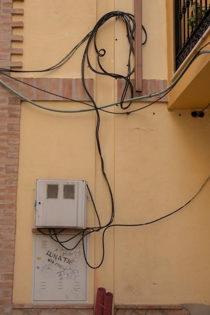
Avoiding common wiring mistakes is critical for a safe and functional manual transfer switch installation. Ensure wires are connected to the correct terminals as per the diagram. Never interchange hot and neutral wires, as this can cause electrical hazards. Verify that the load matches the switch’s capacity to prevent overload. Always follow the manufacturer’s wiring diagram and test connections before energizing the system. Proper installation prevents failures and ensures reliable power transfer during outages. Consulting a certified electrician can help avoid potential errors.
Troubleshooting Common Issues
Troubleshooting common issues involves identifying faulty connections, testing circuit breakers, and verifying power transfer functionality. Always refer to the wiring diagram to ensure proper diagnostics and repairs.
5.1 Identifying Faulty Connections
Identifying faulty connections is critical for ensuring reliable power transfer. Start by reviewing the wiring diagram to verify all connections match the design. Check for loose wires, incorrect terminations, or damaged components. Use a multimeter to test for continuity and voltage drop; Inspect circuit breakers and switches for signs of wear or overheating. Regularly inspecting connections can prevent failures during power outages. Always follow safety protocols when testing live circuits to avoid electrical hazards. Proper identification and repair of faulty connections ensure smooth operation of the transfer switch system.
5.2 Resolving Power Transfer Failures
To resolve power transfer failures, first check the wiring diagram to ensure connections are correct. Verify that the manual transfer switch is in the proper position and all circuit breakers are reset. Test for live voltage at the generator and utility inputs using a multimeter. Inspect switches and connections for damage or corrosion; If issues persist, consult the wiring diagram or manufacturer’s manual for troubleshooting guides. Ensure all components are rated for the system’s capacity. Professional assistance may be needed for complex failures to restore reliable power transfer functionality.

Maintenance and Upkeep of the Transfer Switch
Regularly inspect and clean the transfer switch to ensure optimal performance. Check connections, tighten loose wires, and replace worn or damaged parts as needed for reliability.
6.1 Regular Inspection of Wiring and Components
Regular inspection of the transfer switch wiring and components is essential to ensure reliability and safety. Check for signs of wear, damage, or corrosion on wires and connections. Verify that all terminals are secure and properly tightened. Inspect circuit breakers and protective devices for any tripping issues or wear. Ensure the switch operates smoothly between positions. Schedule inspections annually or after significant power events to maintain optimal performance and prevent potential failures.
6.2 Cleaning and Replacing Worn Parts
Regular cleaning and replacement of worn parts are vital for maintaining the transfer switch’s efficiency. Use a soft brush or compressed air to remove dust and debris from contacts and surfaces. Inspect terminals for corrosion and clean them with a wire brush. Replace any damaged or corroded wires, and ensure all connections are secure. Worn-out components, such as switches or circuit breakers, should be replaced with manufacturer-approved parts. Regular maintenance prevents unreliable power transfer and potential safety hazards.
A manual transfer switch wiring diagram is essential for safe and effective power management, ensuring reliable operation during outages and adherence to electrical standards.
7.1 Summary of Best Practices
Always follow the wiring diagram for your specific manual transfer switch to ensure safe and correct installation. Plan carefully, use proper tools, and test connections thoroughly. Adhere to local electrical codes and perform regular inspections to maintain reliability. Keep the switch clean and replace worn parts promptly. By following these best practices, you ensure seamless power transfer during outages and protect your electrical system from potential hazards.
7.2 Final Thoughts on Safe and Effective Installation
Safe and effective installation of a manual transfer switch requires meticulous attention to detail and adherence to the wiring diagram. Always test the system after installation to ensure proper functionality; Regular maintenance and inspections are crucial to uphold reliability. By following manufacturer guidelines and local electrical codes, you can ensure a safe and efficient power transfer process. Remember, a well-installed system not only prevents hazards but also provides peace of mind during power outages.
